
Inroduction
- The Traveling Grate Furnace is a widely adopted combustion system, especially in industrial-scale biomass boilers.
- Its scope spans across fuel flexibility, high efficiency, and continuous operation, making it suitable for both energy production and process heat applications.
- Here’s a comprehensive look at its scope:
Working Principle of Traveling Grate Furnace
- A Traveling Grate Furnace is a mechanically moving combustion system designed for continuous burning of solid biomass fuels such as wood chips, bagasse, rice husk, and agro-residues.
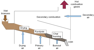
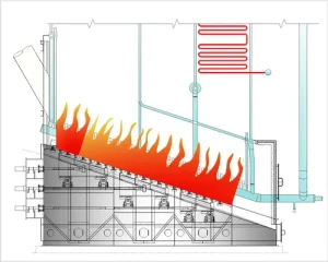
- The moving grate transports fuel through different combustion stages inside the furnace to ensure complete and efficient burning.
| Stage | Process Description |
|---|---|
| 1. Fuel Feeding | Biomass fuel is fed from a hopper or feeder onto the front end of the moving grate (usually via screw or belt conveyor). |
| 2. Drying Zone | As the fuel travels on the grate, it is preheated and dried using hot flue gases from the combustion zone. This reduces fuel moisture. |
| 3. Ignition & Devolatilization | The dried fuel starts to ignite, releasing volatile gases. Primary air is supplied from beneath the grate to support partial combustion. |
| 4. Combustion Zone | The volatile gases and remaining solid carbon (char) undergo full combustion with the help of secondary air, producing high-temperature flames. |
| 5. Burnout Zone | Remaining ash and unburned residues are completely oxidized before reaching the grate end. |
| 6. Ash Discharge | The moving grate delivers the bottom ash to a discharge hopper or ash conveyor for removal and disposal. |
Airflow Management in Grate
-
Primary Air: Supplied from below the grate to aid in drying, ignition, and partial combustion.
-
Secondary Air: Injected above the fuel bed for complete combustion of volatiles.
-
Tertiary Air (optional): Can be added to reduce emissions or improve burnout.
Control Parameters
| Parameter | Function |
|---|---|
| Grate Speed | Controls residence time of fuel; slower speed allows complete combustion. |
| Air Flow Rates | Must be optimized for combustion efficiency and low emissions. |
| Fuel Feed Rate | Should match the combustion rate to prevent overloading or underfeeding. |
Advantages of the Working Mechanism
-
Ensures complete combustion across a moving bed.
-
Allows continuous operation and automatic ash removal.
-
Supports flexible fuel types and moisture content.
-
Enables multi-zone temperature control.
Types and Industrial Applications
Traveling grate furnaces are best suited for:
-
Co-generation plants (CHP) – Simultaneous production of heat and power.
-
Steam generation in textile, paper, rubber, chemical, and food industries.
-
District heating systems using biomass.
-
Process industries with continuous heat requirements.

| Industry | Fuel Types | Recommended Grate Type |
|---|---|---|
| Sugar Mills | Bagasse | Chain Grate or Hybrid Grate |
| Rice & Agro Industries | Rice husk, straw, husk blends | Step Grate or Reciprocating Grate |
| Food & Beverage | Fruit peels, coconut shells, sawdust | Inclined or Chain Grate |
| Textile Industry | Wood chips, agro-pellets | Chain Grate |
| Paper & Pulp | Bark, black liquor sludge, wood residues | Hybrid or Reciprocating Grate |
| Municipal Solid Waste | MSW with biomass content | Reciprocating or Step Grate |
| Biomass Power Plants | Mixed biomass fuels | Hybrid Grate or Step Grate |
Types of Traveling Grate Furnaces and their Applications
| Type of Grate Furnace | Description | Suitable Biomass Fuels | Key Features | Typical Applications |
|---|---|---|---|---|
| 1. Chain Grate Furnace | Continuous metal chain links moving under the furnace | Wood chips, bagasse, briquettes | Simple design, steady fuel feed, good for uniform fuels | Textile mills, food industries, steam boilers (1–20 TPH) |
| 2. Reciprocating Grate Furnace | Grate moves back-and-forth in segments | Palm shells, crop residue, mixed biomass waste | Agitates fuel, handles non-uniform fuels well | Waste-to-energy, agro-waste plants, MSW + biomass |
| 3. Inclined Traveling Grate Furnace | Grate set at an angle to aid natural fuel movement | Coconut shells, low-moisture sawdust | Improved drying, better air distribution | Timber and paper industries, medium-scale cogeneration |
| 4. Step Grate (Pusher Grate) | Multiple steps/zones for staged combustion | Rice husk, bamboo dust, high-moisture fuels | Staged burning: drying → devolatilization → burnout | Rice mills, agro-processing units, captive power plants |
| 5. Hybrid Grate Furnace | Combines chain and reciprocating or step grates | Mixed biomass (seasonal variation) | Versatile, adaptable to varying fuel conditions | Large industrial boilers, flexible-fuel operations |
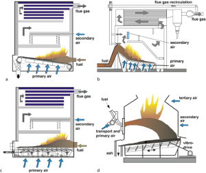
Reciprocating Grate Furnace
-
Description: Grate consists of rows of bars that move back and forth in a stepwise motion.
-
Fuel Suitability: Ideal for non-uniform, coarse biomass like palm kernel shells, crop residues, and mixed waste.
-
Combustion: Enhances fuel agitation for better burnout.
-
Application:
-
Municipal solid waste with biomass blend.
-
Biomass plants in agro-industries.
-
Power generation with mixed fuels.
-
Chain Grate Furnace (Continuous Grate)
-
Description: Made of cast iron or steel links connected in a chain. It moves like a conveyor belt under the combustion chamber.
-
Fuel Suitability: Medium-moisture, granular biomass (e.g., wood chips, bagasse).
-
Combustion: Uniform, suitable for steady fuel sizes.
-
Application:
-
Textile and food processing industries.
-
Small to medium steam generation (1–20 TPH)

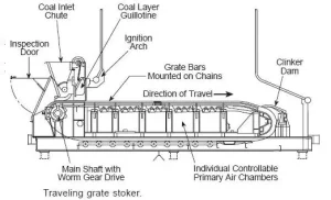
Chain type traveling grate stoker boiler operation
-
Step Grate Furnace (Pusher Grate)
-
Description: Combustion takes place in stages over several steps or levels of grates.
-
Fuel Suitability: High-ash, high-moisture biomass (e.g., rice husk, bamboo dust).
-
Combustion: Controlled burning stages (drying, devolatilization, combustion, burnout).
-
Application:
-
Rice mills, agro-processing industries.
-
Biomass-based captive power plants.
-
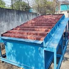
Benefits of Traveling Grate Furnace for Biomass Boilers
Following is a summary of TG furnace benefits
| Benefit | Description |
|---|---|
| 🔁 Continuous Operation | Supports non-stop fuel feeding and ash removal, ideal for 24/7 industrial processes. |
| 🔥 Efficient Combustion | Multi-zone combustion (drying, ignition, burnout) ensures complete fuel burning and higher thermal efficiency (up to 85%). |
| 🌱 Fuel Flexibility | Can handle a wide variety of biomass fuels with varying moisture and ash content (e.g., rice husk, wood chips, bagasse). |
| ⚙️ Controlled Grate Speed | Grate movement can be adjusted to control residence time, ensuring complete combustion based on fuel properties. |
| 💨 Optimized Air Distribution | Primary and secondary air systems ensure better mixing, temperature control, and reduced emissions. |
| ♻️ Low Emissions | With proper combustion tuning and emission controls, it can meet environmental standards (low CO, NOx, and particulates). |
| 🧹 Automatic Ash Handling | Bottom ash is discharged automatically at the end of the grate, reducing manual labor and operational hassle. |
| 🏭 Scalability | Suitable for medium to large capacity boilers (1 to 100+ TPH) used in industries and power plants. |
| 🔧 Ease of Maintenance | Modular grate parts allow for easy replacement and servicing without long shutdowns. |
| 💡 Integration with Automation | Compatible with PLC/SCADA systems for automated control of fuel feed, grate speed, and air supply. |
| 🌍 Supports Sustainable Energy | Ideal for biomass and agro-waste fuels, promoting carbon neutrality and waste valorization. |
| 🧪 Well-Suited for CFD Optimization | Grate and air flow design can be further optimized using simulation tools for better efficiency and heat distribution. |
Continuous and Uniform Combustion
-
The moving grate enables steady fuel feeding and ash removal.
-
Allows continuous combustion without the need for shutdowns or batch feeding.
Fuel Flexibility
-
Can handle a wide range of solid fuels, including:
-
Biomass: wood chips, bagasse, rice husk, sawdust, pellets
-
Low-grade fuels with high moisture or ash content
-
-
Ideal for rural agro-industrial applications using local residues.
High Thermal Efficiency
-
Multi-zone combustion: drying, devolatilization, combustion, and burnout.
-
Efficient air distribution ensures complete combustion.
-
Efficiency can reach 75–85% with proper design and operation.
Easy Ash Handling
-
Automatic ash discharge system at the end of the grate.
-
Reduces clinker formation compared to fixed grates.
-
Suitable for high-ash fuels like rice husk.
Low Maintenance and Robust Operation
-
Mechanically simple and robust construction.
-
Modular grate bars allow for easy replacement and cleaning.
-
Designed for long operational life with minimal downtime.
Scalable for Medium to Large Boilers
-
Suitable for 1 TPH to over 100 TPH steam generation.
-
Ideal for industries requiring constant heat or steam supply.
Compatible with Emission Control Systems
-
Can be paired with:
-
Bag filters
-
Cyclones
-
Scrubbers
-
ESPs (Electrostatic Precipitators)
-
-
Helps meet environmental emission standards.
Automation Friendly
-
Grate speed, air flow, and fuel feed can be automated and optimized.
-
Enables real-time control for combustion efficiency and emissions.
Proven and Widely Accepted Technology
-
Well-established in biomass power plants, captive industrial boilers, and process heating applications.
-
Known for reliability, ease of use, and cost-effectiveness.
Ideal for Retrofitting Coal Boilers
-
Existing coal-fired furnaces can be retrofitted with traveling grates to use biomass, promoting sustainability.
Efficiency and Emission Control
-
Achieves thermal efficiency of 75–85% with proper tuning.
-
Enables multi-zone combustion (drying, volatile release, burnout).
-
Can be integrated with emission control devices like ESP, bag filters, and scrubbers for:
-
Low NOx combustion
-
Reduced particulate emissions
-
Ash handling optimization
-
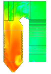
Scope of CFD modeling for traveling grate furnace
- Computational Fluid Dynamics (CFD) plays a transformative role in analyzing and optimizing the thermal and combustion performance of traveling grate furnaces used in biomass boilers.
- Given the complex, multi-physics environment inside these furnaces, CFD modeling offers detailed insight that physical testing alone cannot provide.
| CFD Application Area | Objective / Benefit |
|---|---|
| 🔥 Combustion Analysis | Model volatile release, char burnout, flame shape, and combustion zones to ensure complete burning of biomass. |
| 💨 Air Distribution Optimization | Simulate primary, secondary, and tertiary airflow to improve mixing and reduce CO, NOx emissions. |
| 🌡️ Temperature Profile Analysis | Identify hot/cold spots, uniformity of heat distribution, and avoid thermal stress or slagging. |
| 🧯 Emission Prediction & Control | Predict CO, NOx, and unburnt carbon levels to help design low-emission systems. |
| 🏗️ Grate Design Optimization | Study the impact of grate speed, hole size, and air inlets to maximize combustion efficiency. |
| 🔁 Residence Time and Fuel Flow | Simulate biomass particle motion and residence time to ensure complete combustion before ash discharge. |
| ♻️ Ash Behavior Simulation | Predict clinker formation, ash melting zones, and optimize ash removal. |
| 🧊 Heat Recovery and Boiler Integration | Model flue gas behavior for efficient heat transfer in economizer, air preheater, and superheater sections. |
Advanced Modeling Techniques in CFD
| Technique | Purpose |
|---|---|
| Discrete Phase Modeling (DPM) | Tracks biomass particles across the combustion chamber. |
| Species Transport + Reaction Mechanisms | Simulates volatile release, char oxidation, and emission formation. |
| Radiation Modeling (P-1, DO, Rosseland) | Calculates radiative heat transfer accurately in high-temperature zones. |
| Moving/Rotating Mesh (UDF) | Mimics the physical movement of the grate for realistic modeling. |
| User-Defined Functions (UDFs) | Custom logic for fuel combustion kinetics, ash formation, or dynamic boundary conditions. |
Benefits of CFD-Based Design Over Trial-and-Error
| Traditional Method | CFD Advantage |
|---|---|
| High cost of physical trials | Virtual prototyping reduces cost and time |
| Hard to visualize internal flow | Full 3D visualization of flow, combustion, and temperature |
| Trial-and-error air duct design | Air injection ports optimized before fabrication |
| Limited diagnostics on emissions | Predict and correct emission hotspots before operation |
Conclusion
- The traveling grate furnace offers a robust, efficient, and flexible solution for biomass and multi-fuel boilers.
- Its ability to handle diverse fuels, operate continuously, and integrate with modern control systems makes it a preferred choice for industrial energy generation and sustainable heating.
- The scope of CFD modeling for traveling grate furnaces is vast and essential in modern boiler design, combustion tuning, emissions reduction, and fuel flexibility.